Recordings of some of the modules from the Mungo range.
John Pillans very kindly allowed me to spend some time with a case of his Mungo modules in October. I've finally got round to editing and uploading some of the recordings I made with these instruments:
The demos are comprehensive, but if you want more you can buy the album for the full, unedited recordings (17 tracks, 45+ mins).
The case contained the instruments lined up here as well as the p0 & r0 percussion and reverb modelling units. I was drawn to the w0 oscillator and the g0 granular sampler in particular, so there are more examples of those. For a primer on Mungo modules in use, read my post on the d0 here.
If the d0 took some time to fathom, what to make of a case full of Mungo? Well, I took them one at a time, using modules from my main system to provide a control or familiar ground. Even seemingly simple modules like the mixer had me scratching my head. In general, I think more visual indicators would be helpful to clearly show the status of outputs and modes. And, depending on the module in question, the Zoom function can be a source of confusion. The massive range and detail offered might make them more suited to the studio than the stage. Patching takes patience but the payoff is full flexibility and excellent audio quality.
A few words on the modules themselves: my interest in the g0 was real-time sampling and manipulation of blocks, rather than grains, of sound. In that sense, it's over-spec'd for me but the underlying technology means that the audio is smooth and clean. Of the modules in the case, this is the one I still pine for. I think John got a bit carried away with the hyperbole when describing the w0, but it really does combine a lot of features. It is digital, so factor in some filtering post FM. The f0 is nice if unspectacular but worth remembering that it too is digital and, as such, different. The m0 is the first EG/ VCA/ mixer combo I've had to use an oscilloscope to understand! The p0 percussion, v0 vocoder and r0 reverb are subtle instruments that require the detailed control offered by the Zoom function.
Watch the official videos to get more ideas and information, including on the n0 noise module. Or, if you're in Berlin, you can try some of the modules at Schneidersladen.
A belated thank you to those who came along to the Mungo workshop, Andreas Schneider and the Schneidersbüro staff for hosting us and to John for taking the time to explain the technology and ideas behind his unique designs!
Friday, 5 December 2014
Wednesday, 3 September 2014
Patch Tips #27 - An FM Equivalent
An analogue take on digital FM featuring the Toppobrillo Triple Wavefolder.
Today's Patch Tip is inspired by MitchXI's description of a digital implementation of FM:
" ... in a yamaha style set-up, an oscillator is simply a ramp that goes from zero to one for every cycle - a phase accumulator - that gets fed into a lookup table that converts zero to one values into a sine wave. if you add a second oscillator's sine output to the ramp wave before the sine wave function, you get an fm equivalent ... to have an fm modulation relationship, you simply add the output of one oscillator into the other oscillator's sine wave function. the only digital computations that need to happen are addition, multiplication (for mod index/amount), and a table lookup."
If, like me, you feel digital is cheating, here's an analogue solution:
For the look-up table we can use the TWF's saw-to-sine function. Patch your saw (carrier) to the TWF via a mixer and trim the bias on a single channel to achieve a clean sine. Apply your modulator via a VCA or directly to the mixer and trim the amount of 'FM' to taste. In this example I used two VCOs/ two TWF channels and one modulator. I start with just the one voice which I pan left when I introduce the second voice:
twf-fm-equivalent.mp3
At high modulator frequencies the result is pretty good. Because the saw-to-sine converter is analogue, it is sensitive to variations in amplitude and DC offsets. And, like Phase Modulation, this method has it's limits: If the modulator is too slow the 'FM' effect will be negligible.
This patch won't replace your thru-zero FM or phase modulation VCO - the maximum possible index seems similar to standard linear FM. But if your oscillators only have exponential inputs, the Triple Wave Folder offers another unexpected method of dynamically changing the colour of your sound.
Tuesday, 2 September 2014
A-143-9 Lin-FM & Buchla Saw Modification
How to add a linear FM input to Doepfer's quadrature oscillator and get the weird waveshapes of Buchla's 258 VCO.
The A-143-9 quadrature oscillator is a favourite for FM. Its sine wave is pure and the DC-offset is minimal. This makes it the perfect choice as the modulator in dynamic FM patches. It's a shame then that it itself doesn't have a linear FM input. Fortunately, the fix is simple and the result sounds great, especially in quadrature 'stereo':
A-143-9_linFM.mp3
A-143-9_stereo-linFM.mp3
Most analogue VCOs are linear at heart. To get the response we need for musical pitches, CVs need to be translated. If we bypass the part of the circuit that does this - the exponential converter - we should be able to modulate the VCO in a linear fashion.
This depends on the actual circuit design but, happily, this 'dodge' is possible with the A-143-9. I asked Dieter Doepfer and he identified pin 6 of the top quad opamp (TL084) as the target (see A-126 connection PDF for board layout). A resistor determines the modulation depth. Dieter suggested 100K but I ended up using 68K to allow for some over-modulation.
There is one caveat with this simple modification, but it's a limitation that can also be used to musical effect. Pin 6 is also connected to -12V via R8 (270K). This provides the current needed for the oscillator to work. If the modulation voltage 'robs' the VCO of this current - i.e. at 0V - the oscillator will stop. This is good and and bad: at low audio-rates, over-modulation could sound choppy. On the other hand, we gain the ability to gate the VCO/ LFO on or off, similar to a track-and-hold.
The reason FM-ing the A-143-9 sounds so good is that there's no waveform converter messing things up. Even with the best schemes, the sines on triangle- or saw-core VCOs show their heritage by being either brassy or buzzy. So, a sine-core makes sense if clean FM is a priority. Question is, what do you do if you also want a saw or square?
The latter is easily generated with a comparator. For the saw, we can take inspiration from the Buchla 258's 'funny waveshapes'. We can use a triangle-to-saw converter circuit or a patch:
Patch the sine (0) output of the A-143-9 to a mixer. Patch a multiple of the sine to another mixer (e.g. mh01). Set the channel to 50%. Mix in a 2.5V offset and patch the result to the signal input of a polarizer or DC-coupled ring modulator like the A-133. Patch the cosine (90) to a comparator (A-167, Sport Modulator etc.). Set its threshold to 0V. Patch the comparator's output to the CV input of the A-133 and send the result to the first mixer. Now balance the amount of original sine to get the shape you want. Altering the comparator threshold will yield other shapes. Here's how it can sound when modulated:
A-143-9_buchla258saw.mp3
It's not thru-zero, but the quality of the A-143-9's sine-on-sine linear FM is clean and stable. Given the right C:M ratio it can cover some of the sounds generated by wave-folding. With a little more circuitry to provide a permanent saw/ square output, a pair of these quadrature VCOs could form the basis of a budget timbral VCO.
Saturday, 22 March 2014
Berlin Nights
Had a cracking time with new and old synthesizer friends at Schneiders' Messe Aftershow in Kreuzberg on Thursday night. Look forward to a video including Mark Verbos and Koma Chrisi's funky set.
Highlight: Schneider & Splitradix improv on funk bass and megaphone. Low point: the whisky selection at Zum Goldenen Hahn post aftershow.
If you're in Neukölln next weekend, I'll be playing live at Clockwork#1, a modular synthesizer night hosted by Koma Elektronik.
Hope to see you there!
Clockwork#1
29 March, 20:30
at Drumherum
Lichtenraderstr. 49
12049 Berlin
Wednesday, 5 March 2014
CGS77 Serge 1973 Filter Demo
Sounds of the CGS77, Ken Stone's adaptation of the original Serge filter, are scarce. I hope these recordings help anyone considering this DIY build.
I'm really not a filter man, but the Serge VQVCF is something special. This circuit is its 1973 ancestor. The state variable found in today's systems has been refined with gain compensation and a trigger input. But Ken Stone tells me that the CGS77 is essentially the same core and my ears aren't about to argue.
If you want to hear more, please buy the EP for the unedited recordings and pictures of my build.
Building CGS modules for Eurorack presents the DIY-er with the problem of how to accommodate the PCB. Others have opted for 'best-of' panels, combining several PCBs behind one large interface. My solution was initially based on a false assumption - that I could cut below the CGS77's 'dotted line' to remove the unneeded buffers and mount it vertically.
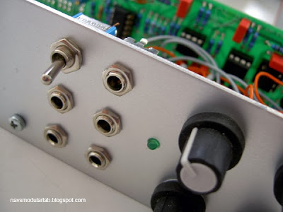
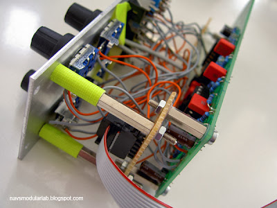
I should have done this before populating the board, so I settled on another tactic. Using stand-offs and making sure the module in the row below is less than 4 cm deep, my '73 filter is a dashing 10HP. Here are the guts and here its installed.
On the mechanics, I used Charlie The Bad Producer's method of attaching the power via a perfboard add-on. I considered normalling the band-pass to the input for self-oscillation, but found in testing that the '73 doesn't make a particularly stable oscillator. The HP & BP are nice, but not as good as the Plan B Model 12, so I might leave them out on a future build. Other casualties might be the DC mode and LED. This filter responds well to modulation, so an additional CV input would be more useful: this can be added in at the points marked S & R on the schematic.
Thank you Serge & Ken for this wonderful filter, negativspace for BOM help and my brother for the boards!
Subscribe to:
Posts (Atom)