Showing posts with label serge. Show all posts

Saturday, 28 October 2017

Powwow 4 - Feedback

Here’s the recording of my live set at the fourth Berlin Powwow session which you can buy from my Bandcamp.


For this performance I wanted to explore feedback and the obstacles and modifiers one can place in the loop. The key players in this were delays, filters, non-linear functions and malfunctioning components.


My main analogue patch featured a Cwejman RES-4 in a loop with a Bananalogue Serge WVX. The combination of four frequency bands of oscillation might have been enough, but placing a Cwejman VCEQ-3 in the chain to dampen or boost the feedback added another level of complexity. A stressed coupling capacitor and scratchy Folds pot on the WVX added to the unpredictability and fun.

Live, I love my Clavia Micro Modular for two main reasons: patch recall, which allows me to set a scene or chop between moods, and polyphony. The virtual feedback patches in this set were simple, but switching them to two or three voices added complexity and interest, for example asynchronous panning or the beating of multiple sine-wave oscillators. You can do it with a ’real’ modular, but at a cost!

This set up is flexible and just about portable. It’s still completely live in that each patch either has to be built or played by hand. But the addition and convenience of the Micro Modular does cause me to question how we approach playing live with a modular. With many musicians turning up to gigs with their rigs pre-patched, is there a difference or even a need for the real deal?

Thanks again to Goldwiener, Hainbach, Paul da Fonk and Mark Berman of Powwow for the opportunity to make some noise.

Thursday, 19 October 2017

Basic Electricity Concert Tonight - Rastko, Plastiq Phantom


If you’re in Berlin tonight, come along to Basic Electricity, a concert with the Serge Animal tamer, Rastko and Patch Point proprietor, Plastiq Phantom, aka Dr. Wiener.

Doors open at 19:30 for music at 20:30 at the König Otto in Neukölln. As you can see, it’s an amazing venue housed in the old Kindl brewery.

There’s more info here and a Facebook event here.

See you later!

BE#23, Thursday, 19.10.17 @ König Otto
Tickets 10€. Doors at 19:30, music at 20:30
Am Sudhaus 3, 12053 Berlin Neukölln
U7 Rathaus Neukölln or U8 Boddinstr.

Sunday, 4 October 2015

Doeper/ Serge VCS Expander Schematic


A description of the method I used to add Hold, Burst and EOR functions to the Doepfer A-171-2. An update to this post. The module is a licenced version of the Serge/ CGS DUSG/ VCS, so these mods will work on them too, although the pins may be different.

You can download the schematics and Fritzing file here. I wish I had done this at the time in spring as I've had to retrace my thoughts from incomplete notes. It's been fun but I might have some things wrong and I’m sure some aspects could be done better. So, please continue the discussion and post corrections and improvements to this circuit in this forum thread. I will update this post accordingly.

HOLD


The idea behind the Hold circuit is simple: interrupt the integrator. If you wanted to go no further and keep this mod passive, all you would need to do is cut one trace and hook up a switch. On the A-171-2, I found a convenient place between pin 7 of the TL084 quad opamp and the 8k2 resistor (R39).

If we want to automate this, we need an analogue switch. Transistors can be fiddly and the common CD4066 won’t process all signals, so I used a DG201. This switch is ‘normally closed’, so with no gate on the command input, drain and source are connected and the integrator’s loop is closed. Pulsing it breaks the connection.

EOR

Referring to Tim Stinchcombe’s VCS analysis and comparing with the Doepfer layout, pin 4 of the LM3900 is high during the attack phase. The ‘not attack’ gate, which will become part of our EOR gate, can be found on pin 5 of the LM3900. If you observe this output with an oscilloscope you’ll notice we need to process it as the ‘not attack’ gate remains high until the next attack phase is initiated. This can have its uses, but it’s not what we’re after if we want an EOR/ variable length gate that can be used to ping filters etc.


This is where we have to get creative and ‘patch with ICs’: we use another switch on the DG201 to operate a logical AND function. The signal which chops our ‘not attack’ gate down to the right length is the EOC gate. We can tap this signal from the End Out jack on the A-171-2. As the EOC gate is ‘high’ at the wrong time, we want to flip its activity.

The need for a logic inverter conveniently also answers the question of how to buffer the inputs for this mod. I used an HCF4049UBC Hex Inverter. As the supply voltage also determines the logic threshold for this chip (lower voltage = lower threshold/ faster response), I chose to run it off 5V, supplied by a 78L05A regulator. I sent the new EOR signal from pin 15 of the switch to a jack and an LED.

BURST

Now that we have the means to process logic, the burst function is relatively simple. It’s a circuit adaptation of the classic Maths Trills patch where we used a logic gate to interrupt the loopback of the EOC signal to the trigger input. As with the EOR gate, we use a switch to function as a logical AND gate. The DG201 is ’normally closed’, so we need to keep the switch open when there is no burst command present. To do this, we use a spare inverter to flip the activity of the burst input. Looking at the schematic on Ken Stone’s site, the trigger and cycle inputs are OR-combined by diodes, so the VCS can be triggered and burst/ cycled at the same time.


The DG201 is powered from +/- 12V. Filter the supply as usual and add 0.1uF bypass caps for the ICs. The burst and hold inputs were conditioned by cutting negative voltages. The schematic says 4001, but I used 4148 diodes.  I added a manual gate by tapping 5V and sending it via an ON-ON switch to either the burst or hold jack’s switching contact.

It sounds more complicated than it is. Once I’d thought it through, I built it on stripboard on the fly, without the need for a detailed schematic. Lesson learned on that score! I hope these notes help and look forward to your comments and improvements.

Thanks to Dieter Doepfer and Chrisi & Erik at Koma Elektronik for their help on the subject of switches.

The usual DIY disclaimer: do this at your own risk, take care and have fun.

Friday, 10 April 2015

A-171-2 VCS Expander

Adding gated hold & burst functions and an End of Rise output to Doepfer’s Serge VCS. An update to this post.


A recent forum thread about the Serge 1973 envelope got me thinking about whether it would be possible to add its hold function to the VCS. Once I’d understood what was needed, a burst and EOR pulse were obvious additions.

Both Burst and Hold can be activated manually or by an external signal. Hold freezes the envelope in its tracks. It’s different to patching via a S&H as the envelope continues where it left off. Burst simply cycles the envelope at will.

Audio examples: Hold (cycling VCS FMs a VCO, button pressed to hold), Burst (first manual, then activated by 2nd row of sequencer).


The EOR is needed for quadrature functions with two envelopes (the other fires at the End of Cycle). Conditioning the pulse required some creative thinking, a case of patching with ICs! Its width can be varied, so it can be used to ping filters or delays.

These modifications are simple to implement with switches and logic inversion (schematic to follow). The additions borrow from my favourite envelopes and make the A-171-2 close to ideal. Yes, I could have just bought a Function but it wouldn’t have been as fun or educational!

Sunday, 22 March 2015

Serge VCS Modification

Modifying the Doepfer A-171-2 Serge VCS for more extreme non-linear curves and more manual control over rise and fall times.


The Serge Voltage Controlled Slope is a classic design and an integral part of many modular musicians’ systems. The Doepfer A-171-2 is a faithful recreation of the original circuit. It works just like the Bananalogue VCS that has been in my case since pre-Maths times. That’s good, and bad.

The VCS easily allows one to set different contours for its rise and fall phases. But its non-linear curves are not as extreme as those possible with Maths. Setting times on the VCS is harder, as the useful range is limited to about 20% of the potentiometer’s throw. It’s these differences between these two similar function generators that this modification tackles.

The feedback that generates non-linear shapes is pre-wired on both the VCS and Maths. Calibrating the VCS output voltage from 5V to 8V has only a marginal effect. But if one patches the VCS envelope output to its ‘Both CV’ input with VC Rise + Fall set to linear, the Serge yields the desired curves. This suggests the internal CV feedback loop is capped.

Indeed, if we look at the left of the schematic, at switches SWF & SWR we find 330K resistors limiting the amount of feedback to the CV mixer to about 30%. If we lower this resistance we’ll get more feedback. I desoldered and replaced the 330K resistors with 200K but you could also try soldering another value in parallel e.g. 150K (= ca. 100K, 100%) or 470K (=ca. 200K, 50%).

This part of the modification helped clear up an oddity about the VCS: namely, why making the curves more exponential actually increases the overall envelope time. Negative feedback should make it shorter, and vice versa.

If we study the same part of the schematic again, we can see -12V across a 1M resistor feeding the summing points. Given the gain ratio set by the 100K resistor, this offsets the rise and fall rates by +/-1.2 volts. I find this counter-intuitive, so I removed both 1M resistors.


Both my Doepfer and Bananalogue modules are fitted with logarithmic potentiometers to manually set the rise and fall rates. This means, when using the VCS as an envelope or slew limiter, changes in the first 50% of the pot’s throw are imperceptible. Typical envelope settings lie between about one and three o’clock. Tapering the A50K potentiometers on the A-171-2 with a 5.6K resistor between the CW/ ‘hot’ lug and the wiper solves this. The useful range now spans from nine to three o’clock.


To solder these in place, you’ll have to unscrew the jacks and remove the board from the faceplate. I tape Gaffa around the ends of my pliers to avoid scratches. While you’re there, you can measure the output between the A50K wipers and the subsequent 82K resistors to understand how the log pots choke the voltage. I did try an S-curve taper with two sets of resistors but the quasi-linearization suggested here by Daverj worked best.

So, what does it sound like? Here are two recordings:

feeback mod: exp-fall, unmodified, 0:08 modded, exp-rise, 0:16 unmodified, 0:23 modded.

pot taper mod: cycling, rise = zero, fall manually altered. Stock VCS then modded at 0:39

These simple changes have given my VCS more whip and made it easier to use. Thanks to Dieter Doepfer for helping me read his PCB layout, Ken Stone for publishing his schematic, Tim Stinchcombe and Dave Jones.

If you’d like to try this yourself, take the usual precautions to avoid damage to yourself or your module. I will not be held responsible. If in doubt, ask Doepfer or your technician to carry out the modifications for you.

Wednesday, 5 March 2014

CGS77 Serge 1973 Filter Demo

Sounds of the CGS77, Ken Stone's adaptation of the original Serge filter, are scarce. I hope these recordings help anyone considering this DIY build.


I'm really not a filter man, but the Serge VQVCF is something special. This circuit is its 1973 ancestor. The state variable found in today's systems has been refined with gain compensation and a trigger input. But Ken Stone tells me that the CGS77 is essentially the same core and my ears aren't about to argue.


If you want to hear more, please buy the EP for the unedited recordings and pictures of my build.


Building CGS modules for Eurorack presents the DIY-er with the problem of how to accommodate the PCB. Others have opted for 'best-of' panels, combining several PCBs behind one large interface. My solution was initially based on a false assumption - that I could cut below the CGS77's 'dotted line' to remove the unneeded buffers and mount it vertically.


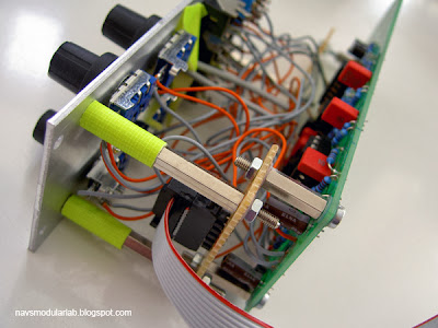
I should have done this before populating the board, so I settled on another tactic. Using stand-offs and making sure the module in the row below is less than 4 cm deep, my '73 filter is a dashing 10HP. Here are the guts and here its installed.


On the mechanics, I used Charlie The Bad Producer's method of attaching the power via a perfboard add-on. I considered normalling the band-pass to the input for self-oscillation, but found in testing that the '73 doesn't make a particularly stable oscillator. The HP & BP are nice, but not as good as the Plan B Model 12, so I might leave them out on a future build. Other casualties might be the DC mode and LED. This filter responds well to modulation, so an additional CV input would be more useful: this can be added in at the points marked S & R on the schematic.

Thank you Serge & Ken for this wonderful filter, negativspace for BOM help and my brother for the boards!

Saturday, 28 September 2013

Patch Tips #26 - Let's Make an Envelope

Deconstructing the AD envelope. An extravagant but enlightening exercise in understanding how triggered slopes work.


I've been looking into the circuits used in attack/ decay envelope generators and thought it might be interesting to patch one from its basic building blocks. I took my clues from a design described by Barry Klein and René Schmitz and Ray Wilson's Skew LFO to come up with the Skew-velope. Here's how it sounds (MP3).

And here's how it works:


A trigger sets a flip-flop high. Its output is slewed. When the slew signal hits a peak threshold, a comparator turns the flip-flop off and the signal starts to fall. When that voltage hits zero volts - i.e. the envelope ends - another comparator turns the flip-flop on and the process begins anew. Feedback helps shape the envelope. Here is a PDF of the patch and modules I used. Ironically, you may find yourself turning to Maths for its secondary functions in your experiments!

So, why use 8 modules to replicate something that can be done with one? It helped me understand the characteristics of these sorts of contour generators. For example, why re-triggers are ignored during the rise phase, making use as a delay/ divider possible. It also helped demystify Maths & its Serge forbears. Analogue envelopes rely on some form of logic and switching to work. These multifunction modules make some of those processes available to the user.

For more, read Tim Stinchcombe's paper on the Serge circuit.

Tuesday, 16 April 2013

Basic Electricity - Concert this Friday

Join us for Basic Electricity #9 this Friday, 19th April when Max Loderbauer makes his solo debut on Buchla 200e synthesizer and Erik Dower goes head-to-head with the Boom Doctor.

More info here. Facebook event here.

BE#9, 19.04.13, Doors: 21:00
Kastanienallee 77 (Kino)
10435 Berlin (Prenzlauer-Berg)


Looking forward to seeing you at BE#9!

Wednesday, 25 July 2012

Anthony Bisset live at Basic Electricity

Anthony Bisset will join Franz Schuier & Lu Katavist at Basic Electricity #5 on Friday, August 31st!


See the Basic Electricity blog for more on the gig and click the 'Machine' link at Anthony's site to see his reformatted modular 'with DNA from Serge, Buchla, Ken Stone & Bisset' and other live instruments.

BE#5, 31.08.12, 21:00
Lichtblick Kino. Kastanienallee 77,
10435 Berlin (Prenzlauer Berg)

Saturday, 4 February 2012

Basic Electricity #2

Live electronic/ acoustic gig in Berlin, featuring Rastko on Ciat-Lonbarde instruments, Hayden Chisholm on alto sax and Sruti box & Richard Scott on Buchla Thunder.


(Click here for full-size flyer)

Auxxx is proud to present an all-star line-up for the second Basic Electricity night. It takes place on February 24th at 21:00. The venue is the small cinema on Kastanienallee 77, 10435 Berlin-Prenzlauer Berg.


http://rastko.info/

Rastko is a composer and improviser of electronic music based in Geneva, Switzerland. He has been composing music for contemporary dance, theatre and television since 1996. At BE#2 he'll be showcasing the unique Ciat-Lonbarde instruments. A video of him playing the Serge with the CocoQuantus can be found here.


http://haydenchisholm.net/

Hayden Chisholm is a New Zealand saxophonist and composer who has been at the forefront of European music scene for over a decade with his groundbreaking microtonal work and unmistakable sound. At BE#2 he'll be improvising a raga with his 'Well Tempered Sruti Box'. Here is a video of it in action.

Our very own Richard Scott needs little introduction. 'Mr. Wizard-Stix' will be wearing his magic wooly hat, casting sonic spells with his Buchla Thunder/ Wireless Gestural Instrument. You can find some of his recent videos here.

The artists will play a solo and a collaboration.

Basic Electricity #2 promises to be a very exciting night, mixing hands-on circuit manipulation, acoustic improvisation and gestural composition. We look forward to seeing you there!

Monday, 5 September 2011

From Bananas to Blippoos

Some pictures from a day in Richard Scott's studio.


Richard's studio is an Aladdin's Cave of Banana-jack synths. The Buchla VCO was on its way to its new owner, so I was lucky to get a chance to hear it. While it looks fantastic, I wasn't taken by its sound. Financially speaking, this is probably a good thing. The Serge & CGS system was much more to my taste. I was surprised at how familiar I was with its patching vocabulary, due in part to certain Serge-inspired Euro modules, and was able to dive straight in. The Bugbrand is a cracking, compact system with a gutsy sound. But of all the synths in the studio, I lost my heart to the two Hordijk boxes, the wonderful Blippoo and Benjolin.

Thanks to Richard for a wonderful afternoon and the pukka pakoras!

Tuesday, 9 August 2011

Patch Tips #17 - Sport Detector

Using the Toppobrillo Sport Modulator as a slope detector.


One of the most interesting aspects of Mono-Poly's performance at the recent Basic Electricity night in Berlin was his use of slope detectors to generate rhythms. Feeding a pair of Ken Stone/ Elby Designs CGS762s with the outputs of his Wiard/ Malekko Noise Rings yielded unpredictable, yet in sync, patterns.


I'd previously tried the patch example in the Sport Modulator manual without much success. Inspired by the results Mono-Poly got from this configuration, I gave it another shot:

Sport Detector by navs

I used an LFO, reset by a clock divider to feed a Wogglebug which sampled the incoming CV at a rate set by a master clock. This CV was sent to the top section of the SM and an inverted version to the bottom. Lag for both sections was @ 2 o'clock. This setting is important as it determines the SM's reaction time and hence the accuracy or otherwise of the resulting gates. When the CV is rising, a gate is output from the top END (left channel), when it's falling from the bottom END (right).

In the examples, I toyed with the clock divider's reset, the LFO speed and also injected some chaos via the Wogglebug. As you can hear, this is a great way to generate pulse patterns on the fly.

Sunday, 21 November 2010

Patch Tips #14 - Sub-Harmonic Division

Using Maths or the VCS to generate sub-harmonic variation.


Today's Patch Tip is cribbed from Seth Nemec's Bananalogue/ Serge VCS demos and the 'Undertone Generator' patch in Rich Gold's Serge book:

"Sub-Harmonic Generator: If a series of triggers are applied to the VCS faster than the total rise and fall times, the module will divide the incoming signal by a whole number. In the audio range the output will be the sub-harmonic series."

The VCS has the benefit of an AC-coupled output, but I feel Maths offers finer control over the settings. As this patch relies on the rise time, Math's EOR pulse can be used to provide an even beefier sub signal.

The technique simply involves patching a mult of your principal oscillator to Maths' trigger input and mixing either the envelope or EOR with the main VCO in a filter etc. Set the response to linear, fall to fully CCW and then gradually increase the rise time. Additionally altering the fall time will give you more control over the timing and hence sub-divisions.

Here's what it can sound like: subharmonix.mp3

The patch relies on the envelope's inability to respond to a second trigger until it has completed its cycle, meaning it will 'skip' pulses and thus generate a lower frequency. You can try this patch with other trigger-able envelopes like the Plan B Model 10, Cwejman CTG-VC or Doepfer A-143-1, bearing in mind that the minimum possible cycle time and trigger response will affect the possible sub-divisions.

Saturday, 31 July 2010

Sport Modulator - Staircase to Heaven?

An overview and demo of the Toppobrillo Sport Modulator, a dual lag + hold/ sample + hold CV processor and generator which takes its cues from a classic Serge design.


The Sport Modulator features two identical but related sections, both of which are capable of smooth & stepped functions, low and audio-frequency oscillation and pulse streams. For more information and patch tips, see the product page and the SSG Wizardry section of the Serge Fans site.

Here's a basic run-though to get started:


LFO sine > SM in. SM out > VCO. Manual modulation of slew rate. Then pulse from same LFO to 4ms SCM, x8 out > SM T/H in. Lag + Hold mode first, then S+H. Hi hat provided as timing reference.

Here's the SM processing some white noise:


Bottom section cycles, end out provides T/H trigger for top section. Manual tweaks.

And here it is processing itself:


Both sections cycling, top > bottom S/H in, comparator out > bottom CV in, bottom end out > top CV in, bottom out > VCA.

And lastly, a variation on an Allen Strange S&H patch:


2 VCOs. One receives all notes, the second gets timed 'grabs': the main sequence is 8 notes long. Taking a shorter or uneven division from a clock divider causes the S&H to grab a different note on each pass. After about 40 seconds you can hear the difference between S&H + T&H modes: the latter lets the note stream pass while the gate is high and then holds the last note when it goes low. The second part of the recording, after 1 minute, uses the SCM to generate triggers at a faster rate than the main clock, opening the doors to staircase madness.

I have to admit, I spent the first five minutes staring at the Sport Modulator not knowing what I was supposed to patch where. The SSG tips were a great help, although there are some differences between the two. Firstly, as mentioned, both sections of the SM are capable of both smooth and stepped functions making it more flexible than its ancestor. However, the SM's cycle function is not gate-able so, while the cycle button provides convenience, some patch possibilities may have been sacrificed.

The build quality and layout are great and the circuit does indeed hold for quite a while without noticeable droop. Cross-modulating two cycling sections can generate chaotic repetitive patterns, with the comparator output documenting the two oscillators' struggle. An LED for the comparator output and 'attenuverters' for the CV ins would have been useful, but their absence in no way spoils the fun. Like the Wogglebug, which covers some of the same ground, the Sport Modulator is greater than the sum of its parts and the musical results are unique.

Wednesday, 28 July 2010

Make Noise Brains

If you didn't spot Brains lurking under my DIY desktop rack in Monday's post, here's another glimpse:


Brains provides sequencing power to Make Noise's Pressure Points, offering some of the functionality of the classic Serge TKB. For a full description, see the product page and make sure you read the manual! I'd never have thought that such a small and seemingly simple clocker could open up so many possibilities. Nice work work, Tony - Brains, Pressure Points & Maths make a cracking team!

Here's a quick example using the stepped out of a Wogglebug to change the direction of a four-note (i.e. one row) sequence. When the random voltage is above 1V, the sequence runs forward. When it's below, it runs backwards. At about 23 seconds, the /6 output of a 4ms RCD steps a sequential switch to add rows 2 & 3 to the chain, creating a 12-note sequence.


Bugbrains

Brains comes with all the necessary cables to connect the unit to two Pressure Points as well as chain the touchplates and is available now from Schneidersbuero. I'll be taking a closer look at the possibilities offered by Brains later in the week. In the meantime, if you have Pressure Points, do yourself a favour and get this module. It's … a no-brainer.